

What if a published load table is accurate but doesn’t verify the deck in your project? Its capacity may be based on a different deck profile, span, support layout, or loading condition than the drawings specify. Verifying load calculations for composite decks means tracing those assumptions through the calculation, not simply checking a capacity value.
That distinction matters because construction-stage deck behavior and final composite-stage performance require separate checks. If the design inputs don’t match the project, a calculation that looks complete may not identify the governing strength or serviceability limit. A disciplined review helps reveal those gaps.
This checklist explains how to compare the selected deck, spans, supports, and load cases with the project design basis, then identify and document the controlling result. Follow the steps to compare calculations with drawings and product information, flag tables that don’t cover the actual conditions, and record engineering decisions clearly. Structured workflows, including tools for generating composite deck load tables, can support consistent documentation, but project-specific engineering review remains essential.
Key Takeaways
- Define verification against the project design basis, including load assumptions, capacity criteria, and required documentation.
- Check construction-stage and final composite-stage conditions separately, using the supports, spans, and loads that apply to each.
- Before comparing capacity results, match the profile, material thickness, span definition, and support conditions to the project.
- Use pass, fail, or hold dispositions and evidence references to make review decisions clear and traceable.
- Structured software workflows can support consistent load-table generation and documentation. Engineers remain responsible for reviewing assumptions and project-specific outputs.
What Verifying Composite Deck Load Calculations Actually Means
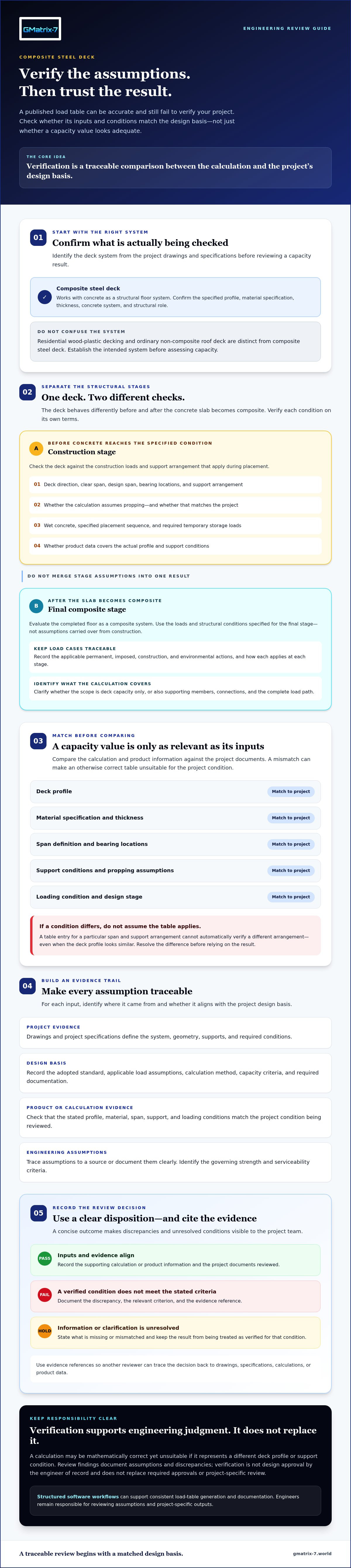
Verification is a traceable comparison between a calculation and the project’s design basis. It checks that the inputs, engineering assumptions, load combinations, capacity criteria, and supporting documents describe the same system shown in the project documents. A calculation can be mathematically correct and still be unsuitable if it uses a different deck profile or support condition.
First, confirm which system the calculation addresses. Composite steel deck works with concrete as a structural floor system. It isn’t residential wood-plastic decking or an ordinary non-composite roof deck, which typically supports loads without relying on composite action with a concrete slab. The phrase “composite decking” can also refer to lumber made from a blend of materials, as explained in this overview of what composite decking is made of. That material is distinct from composite steel deck, so establish the system before reviewing capacity.
Which composite deck system and design stage are being checked?
Start with the project drawings and specifications. Identify the deck profile, material specification, thickness, concrete system, and intended structural role. Then distinguish temporary construction-stage behavior from final composite-floor behavior. Before the concrete reaches the specified condition, the deck may need to support construction loads. The completed floor is evaluated as a composite system. Confirm whether the calculation covers deck capacity only or also supporting members, connections, and the complete load path. These are different review scopes.
What does a verified result need to demonstrate?
Trace each input to its source: a drawing, project specification, adopted standard, or clearly documented engineering assumption. Confirm that the design method matches project requirements and identify the strength and serviceability criteria that govern. A load table or software output applies only to its stated profile, material, span, support, and loading conditions. If a project condition differs, the output alone doesn’t verify that condition.
Calculation verification checks whether the stated analysis matches the project design basis. It does not constitute design approval by the engineer of record. A reviewer can document discrepancies, evidence, and dispositions, but verification doesn’t replace professional judgment, required approvals, or project-specific review. In practice, verifying load calculations for composite decks means checking both the technical result and the traceability of the assumptions behind it.
Trace Composite Deck Loads Through Construction and Service
Follow the deck through each condition it must resist. Start with the project’s governing design documents and identify the specified permanent, imposed, construction, and environmental actions. Record the source of each load and how it applies at each stage. Don’t assume a load included in the completed-floor analysis is also included in the temporary construction check, or vice versa.
Construction-stage and final-stage checks are separate verification tasks because the deck supports different loads and relies on different structural behavior before and after the concrete slab becomes composite. Keeping the stages distinct helps reviewers catch assumptions that might otherwise be obscured by a single capacity result.
How should construction-stage assumptions be checked?
Compare the calculation with the drawings for deck direction, clear span, design span, bearing locations, and support arrangement. Confirm whether the design assumes propping. Don’t treat a propped condition as unpropped, or the reverse, without documented justification. Check that the construction load basis accounts for wet concrete, the specified placement sequence, and any temporary storage loads required by the project. Then confirm that the selected product data covers the actual profile and support conditions.
For example, a table entry for a particular span and support arrangement can’t automatically be applied to a different arrangement just because the deck profile looks similar. Resolve differences before relying on the table. The Steel Deck Institute’s Floor Deck Design Manual is a relevant reference for steel floor deck design. Check that the specific data or method used matches the project and its governing design basis.
What changes in the final composite stage?
For the completed-floor stage, reconcile the assumed concrete properties, slab geometry, reinforcement, and composite design basis with the specifications and drawings. Include supported finishes or services when they form part of the project load basis. Trace the intended load path from the slab and deck into beams or joists, then onward through columns and connections. A deck-level check alone doesn’t establish that every supporting element has been verified.
Confirm that the stated strength, shear, and serviceability checks use the project’s design method and criteria. Record which check governs, and flag missing or inconsistent information instead of silently substituting assumptions. Teams generating tables may use composite deck load-table tools to support a repeatable workflow, while retaining project-specific review and engineering judgment. This stage-by-stage discipline is central to verifying load calculations for composite decks.
Compare Calculation Results with the Right Composite Deck Evidence
A capacity result is useful only if its assumptions match the project. Before comparing numbers, reconcile the deck profile, material thickness, span definition, support condition, and load basis. A similar-looking profile or nearby table entry doesn’t show that the project condition is covered.
Use a comparison record to connect each project input to the calculation assumption, its source, and the reviewer’s disposition. For example:
Project input
Calculation assumption
Supporting evidence
Reviewer disposition
Deck profile and thickness
Profile designation and material thickness used
Project specification and current product data
Pass, fail, or hold; record evidence reference
Span and support
Span definition, continuity, and boundary conditions
Structural drawings and table notes
Pass, fail, or hold; explain any discrepancy
Loads and design method
Load basis and ASD or LRFD method
Design documents and calculation criteria
Pass, fail, or hold; identify unresolved items
Which source should support each calculation input?
Use current, product-specific technical data. Check its revision, units, scope, and limitations. Confirm the project’s design basis, applicable adopted standards and editions, and any jurisdictional amendments. Record whether each value comes from a published table, a calculation, testing, or project-specific engineering documentation. The ANSI/SDI C-2017 Standard for Composite Steel Floor Deck-Slabs is a relevant reference. Verify that it applies to the project’s governing criteria rather than assuming it controls every project.
How can a review expose mismatched table assumptions?
Compare the table’s span definition and continuity assumptions with actual support spacing and boundary conditions. Check the exact profile and material properties, not just a similar product designation. Also flag missing criteria, unchecked unit conversions, and unsupported extrapolation.
Keep demand and capacity distinct. Demand describes the effect of applied loads, while an allowable-load or resistance value describes a limit evaluated under its stated method. Don’t compare an ASD value with an LRFD result as if they were interchangeable. Use a consistent calculation method and criteria, then document the governing comparison and its evidence.
Interpolation, extrapolation, and unlisted conditions require documented engineering justification. A nearby table value is not, by itself, verification. This evidence-based approach makes verifying load calculations for composite decks a traceable review, not a visual match between numbers.
Use This Checklist to Verify Composite Deck Calculations
Apply the same review sequence to each calculation package. For every item, record a pass, fail, or hold, with an evidence reference such as a drawing number, specification section, product-data revision, or calculation page. A hold means there isn’t enough information to confirm the assumption. Don’t fill gaps by silently substituting a nearby table value or undocumented input.
- Confirm the design basis. Check the project’s governing code basis, design method, units, applicable criteria, and documented engineering assumptions. Record the status and cite the design-basis document or calculation reference.
- Confirm document revisions. Compare the calculation with current drawing and specification revisions. Record the status and identify the revision or mark that supports your review.
- Reconcile materials and geometry. Compare the deck profile, material specification, thickness, span definition, and slab information with the project documents. Record the status and cite the product data and drawing references.
- Verify supports and configuration. Check actual spans, support conditions, openings, cantilevers, and construction sequencing against the calculation inputs. Record the status and reference the relevant plans, sections, or details.
- Trace loads and combinations. Confirm each load category and combination comes from project documents or an approved, documented assumption. Record the status and cite the source for each relevant load case.
- Review stage-specific results. Check the stated demand-to-capacity results and applicable deflection criteria for each relevant stage. Confirm the design method is consistent throughout. Record the status and reference the governing calculation pages or table entry.
- Document exceptions and disposition. Record unresolved items, the reviewer, review date, and the software or table revision used. Mark the result as accepted, rejected, or held for resolution, and identify who must address each open issue.
How should discrepancies be handled?
Resolve a failed or held item before accepting the calculation. Missing product evidence, inconsistent units, a changed support layout, or an unlisted condition can affect whether the result applies. Refer nonstandard conditions and design changes to the responsible engineer. Don’t assume a reviewer can approve them by adjusting an input without documented justification.
This sequence makes verifying load calculations for composite decks a project-level audit, not simply a check that a table value looks adequate. For additional context on using a composite deck load table generator guide, review how table inputs relate to stated design conditions. Teams generating composite deck load tables can also explore GMatrix-7 engineering software as a workflow option. Software supports repeatable documentation, while project-specific engineering review remains essential.
Make Composite Deck Load-Table Generation More Traceable
Repeatable software workflows can help teams organize inputs and generate composite deck load tables consistently. Their value depends on careful setup and review. Engineers still need to confirm that the assumptions match the project and that each output is appropriate for its stated use. A generated table is supporting evidence, not project-specific approval.
What should engineers evaluate in a load-table workflow?
Before relying on a workflow, check which inputs the current module supports and whether they cover what’s needed for the intended table, such as profile, span, material, loading, and design basis. Review the output for stated units, assumptions, applicable conditions, and limitations. Confirm the current GMatrix-7 module’s specific input options and reports before describing or relying on them. Don’t assume capabilities that haven’t been checked.
Keep a traceable record for each generated table. The project file should connect the result to:
- The input basis and applicable design criteria
- Controlled product data and its revision
- The calculation method and source of supporting values
- The table output revision and its intended conditions
- Review status, reviewer comments, and any exceptions
How does documentation support a defensible engineering review?
Link calculations and table outputs to the correct product data and project revision so a reviewer can reconstruct what was checked. Keep comments and engineering decisions with the exceptions, rather than leaving the rationale in informal notes. If a profile, span, or design assumption changes, the records should help identify which output needs renewed review.
GMatrix-7 provides tools for generating composite deck load tables and automating structural engineering documentation. Used within a controlled workflow, these tools can support repeatable table generation and organized records. The engineer remains responsible for reviewing assumptions and outputs. For broader context on professional structural design automation, consider how structured documentation fits into engineering review processes.
For your team’s table-generation and documentation workflow, review GMatrix-7 composite deck load-table tools and confirm the current module’s inputs and documentation outputs against your requirements.
Make Every Calculation Easier to Trace
Reliable verification depends on more than a capacity figure. Confirm that project inputs match the drawings and product data, assess construction and final composite stages separately, and connect each result to its evidence. A clear pass, fail, or hold disposition helps surface unresolved assumptions before they are accepted.
That’s the value of verifying load calculations for composite decks through a repeatable review process: decisions are easier to follow, and the basis for engineering judgment stays visible. Organized records should link the design basis, product information, calculation method, output revision, and review status.
GMatrix-7 offers tools for generating composite deck load tables and automating structural documentation and material information. These tools can support consistent workflows, while engineers retain responsibility for reviewing assumptions, outputs, and project-specific requirements.
Explore GMatrix-7 composite deck load-table tools to see how they may support your team’s table-generation and documentation workflow. With disciplined checks and traceable records, you can move forward with greater clarity.
Frequently Asked Questions
What does verifying a composite deck load calculation involve?
Verifying a composite deck load calculation means checking that its inputs and results align with the project design basis. Review the geometry, deck properties, support conditions, loads, design criteria, and documented assumptions. Assess construction and final composite stages separately where applicable. Compare results with current product-specific evidence, record discrepancies and their disposition, and identify the governing checks. Verification supports engineering review. It doesn’t constitute approval or replace the responsible engineer’s project-specific judgment.
How do you check a composite deck load table against project calculations?
Match the exact deck profile, material thickness, span definition, support arrangement, and design method before comparing values. Then check the table’s stated loads, limits, and conditions against project demand and criteria. Verify units and continuity assumptions, and confirm the table applies to the construction or final stage under review. A table entry for a different support layout, for example, may not represent the project. Unlisted or extrapolated conditions need documented engineering justification.
What is the difference between construction-stage and composite-stage deck calculations?
Construction-stage checks assess the deck and supports before the concrete slab develops the assumed composite behavior. Final composite-stage checks use the specified slab and composite design assumptions. Loads, structural behavior, and supporting evidence can differ between these stages, so one check doesn’t automatically cover the other. Verify both when the project requires them, accounting for the actual construction sequence and design basis. Document the conditions each calculation covers and flag any gaps for review.
Which loads should be included when verifying composite deck calculations?
Use the project design documents and applicable adopted requirements to establish relevant permanent, imposed, environmental, and construction loads. The required categories and combinations depend on the project, location, use, and design basis. Check that each load is assigned to the correct stage and that temporary placement or storage conditions are addressed where applicable. Don’t apply residential deck defaults to composite steel deck calculations. Confirm the project-specific basis and refer unclear assumptions to the responsible engineer.
Can I use a manufacturer load table as the only verification?
A manufacturer load table provides product-specific capacity information, but it supports only the conditions stated in that table. Confirm that the profile, thickness, span, support arrangement, loads, criteria, and design method match the project. The table alone doesn’t verify the complete load path or resolve an unlisted condition. Record how the table compares with the project calculation, and refer deviations, limitations, or ambiguities to the responsible engineer before accepting the result.
How should ASD and LRFD results be compared?
Keep the selected design method consistent across loads, allowable or resistance values, and comparison criteria. ASD and LRFD use different formats, so don’t compare a value from one method directly with demand from the other. Check that the calculation identifies its method and relevant factors, then confirm the table or software output uses a compatible basis. If the method or a conversion is unclear, pause the comparison and refer it to the responsible engineer.
Can structural software verify composite deck calculations automatically?
Software can support consistent workflows and generate structured load-table outputs, but it can’t remove the need to review inputs, methods, product data, and project fit. An output depends on suitable assumptions and correct information. GMatrix-7 offers tools for generating composite deck load tables and automating structural documentation and material information. Confirm the current module’s documented capabilities, inputs, and outputs, and have the responsible engineer review results for project-specific use.


