

What if the biggest risk in a metal building design isn’t a single calculation, but an assumption that changes as the project moves from engineering to drawings and materials? That’s where common metal building design mistakes often begin. Loads, framing behavior, component details, and project criteria may seem consistent in isolation while still conflicting across documents.
It’s understandable to focus first on structural calculations. But incomplete criteria and late design changes can also create coordination gaps, rework, and approval delays. Catching those issues early gives project teams a clearer basis for review and decision-making.
This practical checklist covers high-impact checks for loads, framing and component coordination, base and opening conditions, code criteria, and documentation. You’ll learn where assumptions need confirmation, how to compare calculations with drawings and material records, and when to request engineering review. Structured design tools can support consistent documentation workflows, but they don’t replace qualified engineering judgment or project-specific verification.
Key Takeaways
- Confirm occupancy, building geometry, intended use, site conditions, and project performance requirements before design decisions advance.
- Check that load assumptions and load paths align with the project’s governing criteria and applicable standards.
- Review strength, stability, and serviceability separately to uncover overlooked design assumptions.
- Use a pre-issue sequence to compare model inputs, calculations, drawings, openings, interfaces, and document revisions.
- Many common metal building design mistakes persist when teams rely on software alone. Establish criteria, coordinate outputs, and resolve exceptions through structured review.
Common Metal Building Design Mistakes Start with Unclear Project Criteria
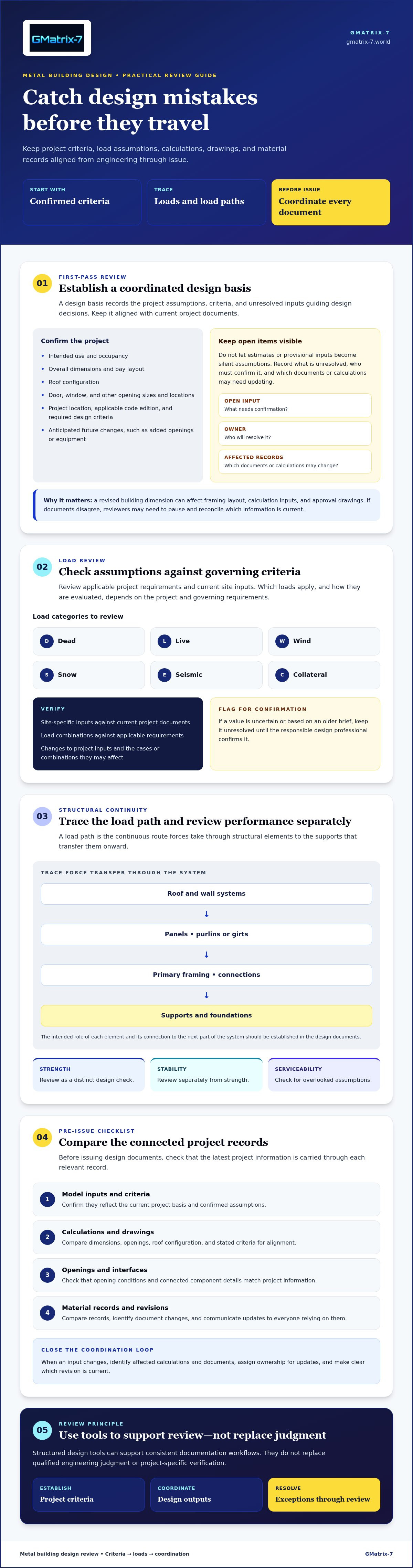
Use this first-pass checklist to confirm the information that will shape the design before calculations and drawings move forward. Early assumptions influence framing layouts, load evaluation, openings, and component selection. If the project brief leaves a requirement open, record it for confirmation rather than letting different team members make separate assumptions.
A design basis is the coordinated record of project assumptions, criteria, and unresolved inputs used to guide design decisions. Keep that record aligned with the project documents. A steel frame depends on connected members working as a structural system. This steel frame building technique illustrates why a change to one part of the building can affect coordinated design work elsewhere.
What project information should be confirmed before design?
Confirm the building’s intended use and occupancy, overall dimensions, bay layout, roof configuration, and the size and location of doors, windows, and other openings. Ask whether future modifications, such as added openings or equipment, are anticipated. Also confirm the project location, applicable code edition, and required design criteria with the responsible project team. Requirements can vary by jurisdiction, so don’t assume that a code edition from a prior project applies.
Capture missing or provisional information explicitly. A short criteria log can identify each open item, who must resolve it, and which documents or calculations may need updating. This is more dependable than silently treating an estimate as a confirmed input.
Why do inconsistent assumptions create downstream risk?
Consider a revised building dimension. It may change the framing layout, affect calculation inputs, and require approval drawings to be revised. If one document reflects the new dimension while another retains the earlier one, reviewers may need to pause and reconcile the difference. That clarification cycle can delay decisions and make it harder to establish which information is current.
Before issuing design documents, compare calculation inputs with the latest architectural and project documents. Check dimensions, openings, roof configuration, and stated criteria for alignment. Then establish who owns each update and how revisions will be communicated to everyone relying on the affected information. These basic controls address common metal building design mistakes at their source: assumptions that drift apart as work progresses.
Avoid Metal Building Load and Load-Path Mistakes
Load decisions need to remain connected to the project’s governing criteria from initial inputs through calculations and drawings. A missed load, an outdated site assumption, or a load combination that doesn’t match applicable requirements can undermine coordination, even when individual documents appear complete. This section is a review guide, not an exhaustive interpretation of building codes or design standards. The responsible design professional must confirm project-specific requirements.
A load path is the continuous route forces take through structural elements from where they act to the supports that transfer them onward. If that route isn’t clearly established in the design, a component may be assumed to transfer force without a documented basis. That’s one of the common metal building design mistakes a deliberate review can help expose.
Which load assumptions deserve a deliberate check?
Review the project’s applicable criteria for dead, live, wind, snow, seismic, and collateral loads. Which loads apply and how they’re evaluated depend on the project and governing requirements. Verify site-specific inputs and load combinations against current project documents, not an older brief or an unconfirmed assumption. Flag uncertain values for confirmation by the responsible design professional instead of treating them as settled.
Check for consistency across the criteria record, calculations, and drawings. If a project input changes, identify which load cases or combinations might be affected and confirm that the revision reaches the documents that rely on it.
How can a broken load path hide in the design?
Trace force transfer from the roof and wall systems toward the supports. Depending on the design, that review may involve panels, purlins or girts, primary framing, connections, and foundations. The goal isn’t to assume every component carries every force. It’s to verify that the design documents establish the intended role of each element and its connection to the next part of the system.
Pay close attention to conditions that can interrupt or redirect the expected route:
- Openings: Confirm that doors and other openings appear in coordinated design information and that their effects are addressed by the responsible designer.
- Equipment and attachments: Check that relevant locations and requirements are communicated, rather than presumed to be included in the original design.
- Interfaces: Verify that the design clarifies how connected components transfer forces, especially where responsibility or supporting information comes from different project documents.
For metal building teams, structured design and documentation workflows can help keep related project information organized, but they don’t replace engineering judgment or verification. Explore metal building design software as one tool for supporting a coordinated workflow, and confirm project-specific load criteria with the responsible design professional.
Catch Metal Building Stability, Member, and Serviceability Oversights
A member can satisfy a strength check and still raise questions about stability or how the building performs in use. Strength checks assess whether a component can resist specified forces under the design criteria. Stability checks consider whether members and the overall structure remain stable given their supports, restraint, and bracing assumptions. Serviceability checks address movement and functional performance. Treating these as separate review questions helps reveal common metal building design mistakes that a capacity check alone may not catch.
Member selection isn’t a matter of choosing the largest section or comparing a single capacity value. The member’s role, span, restraint conditions, connections, and interaction with the rest of the structural system matter. The relevance of each factor depends on the project configuration and governing criteria, so the responsible engineer must verify the design assumptions.
Where do stability and bracing assumptions get missed?
Review overall stability, individual member restraint, and bracing locations as connected parts of one system. Drawings should communicate intended bracing locations and continuity clearly enough for the project team to coordinate them. Where relevant, confirm that design assumptions also reflect the actual configuration and erection sequence. If a brace, support, or restraint is assumed in calculations but isn’t identified or coordinated in project information, request clarification before relying on that assumption.
| Design question | Overlooked assumption | Review action |
|---|---|---|
| Is overall stability addressed? | The structure’s behavior is assumed to follow from member checks alone. | Ask the responsible engineer to confirm the stability approach for the project configuration. |
| Are members adequately restrained? | Bracing or restraint is assumed without clear locations or continuity in the drawings. | Compare documented restraint assumptions with coordinated design information. |
| Will movement suit building functions? | Strength compliance is treated as proof that deflection or movement is acceptable. | Check project-specific serviceability criteria and interface requirements. |
Why should serviceability be checked separately from strength?
Deflection and movement can affect how cladding, doors, equipment, and connected components function, even when strength requirements are addressed. Review the applicable project criteria and standards for acceptance requirements. Don’t apply a universal limit without confirming that it governs the project. Check that interfaces can accommodate expected structural movement and that relevant assumptions are coordinated across calculations and drawings.
Escalate unclear restraint conditions, bracing details, or movement criteria for engineering review. A structured review can help keep assumptions visible, but project-specific verification remains essential.
Prevent Detailing and Coordination Mistakes with a Pre-Issue Checklist
A disciplined pre-issue review connects the design basis to the documents teams will rely on. Use the sequence below to find discrepancies before approval drawings and material documentation are issued. It supports coordination, but it doesn’t certify the design or replace review by the responsible professionals.
What should engineers and detailers cross-check?
- Verify model inputs. Compare grids, elevations, dimensions, openings, roof configuration, and other key inputs with current project documents. Record unresolved differences rather than choosing one version without confirmation.
- Review calculations against the design basis. Confirm that calculation assumptions reflect current criteria and coordinated project information. Flag changes that may affect framing, connections, or component requirements for engineering review.
- Coordinate drawings and interfaces. Reconcile member marks, dimensions, and opening locations across drawings. Check that connection and support assumptions are communicated to relevant project participants, especially where components meet or rely on one another.
- Compare material documentation. Confirm that material schedules reflect the approved design revision and match the intended member and component information. Automated bill of material generation can support a consistent workflow, but the resulting information still requires project-specific review.
- Control revisions before issue. Identify the current document set using clear revision identifiers. Confirm that updates have reached affected calculations, drawings, and schedules before releasing them for review.
These checks target common metal building design mistakes that occur when one document advances while related information stays behind. For example, a revised opening may appear on a drawing but not in the calculation inputs or material schedule. Log and resolve the mismatch rather than treating either document as automatically correct.
How can revisions and reviews reduce coordination errors?
Use a controlled source for current project documents so reviewers aren’t comparing different revisions. Assign reviewers defined scope areas, such as model inputs, connection assumptions, openings, or material schedules. Record open technical questions with an owner and disposition, then verify that the resolution appears consistently in affected documents.
For a closer look at material-list consistency, review automated steel bills of material. Structured tools can generate approval drawings and bills of material to support reviewability, but they don’t guarantee error-free documentation or replace qualified engineering judgment.
To support a coordinated documentation workflow, explore GMatrix-7 design and detailing software and confirm that the selected module aligns with the project’s structural system.
Use a Structured Review Workflow, Not Software Alone, to Reduce Design Mistakes
Design software can organize calculations and documentation, but it can only work from the inputs and assumptions provided. It shouldn’t be treated as a substitute for project-specific review or as a guarantee that every coordination issue will be detected. Many common metal building design mistakes arise when project criteria, model inputs, and issued documents drift out of alignment. Establish a repeatable review cycle around the tools your team uses.
- Establish criteria: Confirm the project’s governing requirements and record unresolved inputs.
- Check inputs: Compare model data with current project documents before relying on generated outputs.
- Coordinate outputs: Review calculations, drawings, and material information together for consistency.
- Resolve exceptions: Document discrepancies and assign them to the responsible reviewer before issue.
What can design and detailing software support?
Use software suited to the structural system and applicable design framework. GMatrix-7 includes modules for Metal Building Systems (IBC), Open Web Steel Joists (SJI), and Light Gauge Steel (AISI). Its tools can generate approval drawings and bills of material to support a consistent documentation workflow. Load table generation is relevant when the project requires tables for single-skin panels, sandwich panels, or composite decks.
Generated outputs still need review against the design basis and current project information. For projects involving metal building systems, MBS IBC design software and compliance workflows provide additional context on how a dedicated workflow can support design and documentation coordination.
When should a qualified engineer make the final determination?
Qualified engineering review is essential for confirming project criteria, assumptions, calculations, and coordinated deliverables. Escalate conflicting inputs, unusual configurations, and unresolved technical questions rather than allowing software defaults or incomplete documents to decide them. The responsible professional should determine whether the available information supports the project-specific design and whether revisions require further review.
Use the tools to make information easier to organize and review, while keeping engineering judgment central to decisions. Explore GMatrix-7 structural design software to see the available modules and documentation-generation capabilities.
Carry a Coordinated Design Basis Into Your Next Review
The most preventable common metal building design mistakes often begin when project assumptions stop matching the calculations, drawings, and material records. A clear design basis, deliberate load-path and serviceability checks, and a controlled pre-issue review give the team a practical way to identify gaps while they can still be clarified. Treat unresolved inputs as review items, not details to leave implicit.
Design software can help teams organize this work, but it doesn’t replace qualified engineering judgment or project-specific verification. GMatrix-7 includes modules for MBS (IBC), OWSJ (SJI), and LGS (AISI) workflows, along with automated approval drawing and bill of material generation. Where required, it also generates load tables for single-skin panels, sandwich panels, and composite decks. These capabilities can support coordinated documentation when teams review outputs against current project criteria.
Explore GMatrix-7 structural design software to see which workflow may fit your structural system. With clear criteria, connected documents, and the right professional review, your team can move forward with greater confidence.
Frequently Asked Questions
What are the most common metal building design mistakes?
The most common metal building design mistakes involve gaps between project criteria, structural assumptions, and issued documents. Examples include incomplete project inputs, loads that don’t match current criteria, unclear load paths, overlooked movement requirements, and drawings that show outdated dimensions or openings. Which issues matter most depends on the building system and design scope. Use a checklist to guide review, not to replace project-specific engineering judgment.
How do you prevent errors in metal building design?
Prevent errors by documenting the design basis, confirming inputs, and coordinating calculations with current drawings and material documentation. Establish revision control so the project team can identify current information, and assign responsibility for resolving open questions. For example, if an opening changes, check whether related calculations, framing details, and schedules need review. Have a qualified design professional assess engineering decisions and applicable project requirements.
Why is load path important in metal building design?
A load path matters because it describes how forces travel through connected structural elements to their supports. If the assumed transfer isn’t represented in the design information, a connection or component may be overlooked or misunderstood. Review the intended route through relevant roof and wall elements, framing, connections, and supports. The actual load path depends on the building configuration, so confirm assumptions with the responsible engineer.
What loads should be considered when designing a metal building?
Consider the loads required by the building’s location, use, configuration, governing code, and project criteria. Depending on the project, these may include dead, live, wind, snow, seismic, and collateral loads. This list isn’t a complete specification for every building. Confirm required load inputs, combinations, and applicable code edition with the project’s qualified design professional, and flag uncertain site or use assumptions for confirmation.
Can structural design software prevent every metal building design mistake?
No. Structural design software can support repeatable calculations and help generate drawings and documentation, but it can’t independently confirm every project assumption or replace professional judgment. Users must provide appropriate inputs, coordinate outputs, and review exceptions. GMatrix-7 offers modules for MBS (IBC), OWSJ (SJI), and LGS (AISI) workflows, plus automated approval drawings and bills of material. Project-specific engineering review remains essential.
Why do metal building design drawings need coordination?
Drawings need coordination because project teams rely on them to communicate dimensions, openings, member marks, connection assumptions, and revisions. If these details conflict with calculations or material documentation, reviewers may need clarification before relying on the information. Compare documents against the current design basis before issue, and use clear revision identifiers. Record discrepancies and confirm their resolution across affected documents rather than assuming one file is authoritative.
What should be checked before issuing metal building design documents?
Before issue, verify that the design basis and project inputs are current, then review calculations, load paths, stability assumptions, member requirements, and serviceability criteria. Check openings, interfaces, connection assumptions, drawing revisions, and material schedules for consistency. Record unresolved questions and refer them to the responsible reviewer. The precise checklist should reflect the project scope and governing requirements. Completing it doesn’t certify the design or replace engineering review.


