
Structural integrity in high-seismic zones isn't achieved by adding more steel, but through the mastery of precise, interconnected load paths. As we approach 2026, the margin for error in cold-formed steel engineering has vanished. You're likely managing the evolving seismic design considerations for LGS framing while facing the persistent fear that manual detailing might fall short of rigorous AISI S400 standards. It's a high-stakes environment where traditional workflows often lead to costly bottlenecks and compliance risks.
This article ensures you master the technical nuances of seismic-resistant light gauge steel design while optimizing for modern building codes and advanced automation. You'll gain a clear understanding of LGS seismic load paths and a reliable framework for total AISI S400 compliance. We'll also explore how GMatrix-7 / LGS (AISI) transforms these intricate requirements into streamlined, automated outputs. We'll start by deconstructing the fundamental mechanics of seismic resistance before moving into the specialized tools that guarantee engineering excellence in every project.
Key Takeaways
- Master the essential seismic design considerations for LGS framing to ensure structural resilience and code compliance in high-risk zones.
- Decode the technical requirements of AISI S100 and AISI S400 to maintain a rigorous standard of safety throughout the engineering process.
- Identify high-value detailing strategies for boundary elements and strap bracing that optimize lateral force-resisting systems.
- Understand how the superior strength-to-weight ratio of cold-formed steel reduces inertial forces to challenge common misconceptions about material ductility.
- Discover how GMatrix-7 / LGS (AISI) automates complex load calculations and drawing generation to eliminate manual detailing bottlenecks.
Understanding Seismic Forces in Light Gauge Steel (LGS) Structures
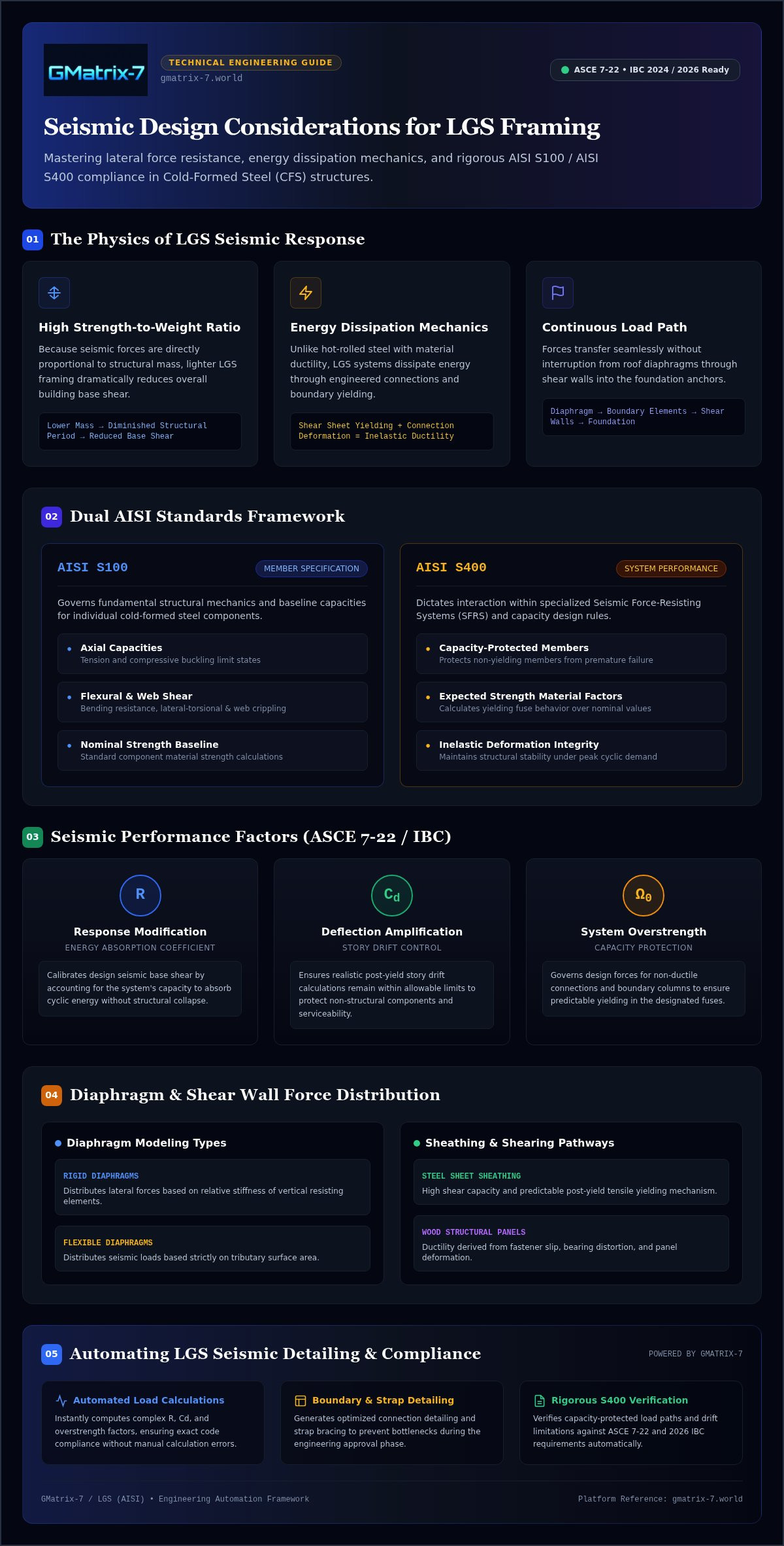
Seismic resilience in modern engineering hinges on the management of mass and momentum. LGS framing provides a decisive advantage through its superior strength-to-weight ratio. Because seismic forces are directly proportional to a building's mass, a lighter structure naturally experiences lower base shear during a ground motion event. This fundamental physics makes LGS a premier choice for mid-rise projects where reducing the overall structural weight translates to more efficient foundations and lower material costs.
Engineers must look beyond simple weight reduction to understand the nuanced seismic design considerations for LGS framing. Unlike hot-rolled steel, which relies on the inherent ductility of the material, LGS systems achieve energy dissipation through the strategic design of connections and boundary elements. We define ductility in this context as the system's ability to undergo significant inelastic deformation without a total loss of strength. When paired with the Response Modification Coefficient (R-factor) and Overstrength (Ω0), these parameters dictate how the lateral force-resisting system (LFRS) performs under peak loads.
The Physics of LGS Seismic Response
The lightweight nature of cold-formed steel significantly lowers the structural period of the building. By reducing the mass, you effectively diminish the seismic demand on the entire frame. Energy dissipation occurs primarily through the yielding of steel sheets in shear walls or the localized deformation at screw and bolt connections. A continuous seismic load path ensures that lateral forces are effectively transferred from the roof diaphragm through the vertical shear walls to the foundation without structural interruption.
Seismic Performance Factors (R, Cd, Ω0)
Selecting the correct R-factor is critical for ensuring ASCE 7-22 and IBC 2024/2026 compliance. For instance, cold-formed steel special bolted moment frames carry different response factors than shear walls sheathed with wood structural panels or steel sheets. These coefficients allow engineers to calculate the design seismic base shear while accounting for the system's inherent ability to absorb energy. Precise application of the Deflection Amplification Factor (Cd) ensures that story drifts remain within allowable limits, protecting non-structural components and maintaining the building's serviceability after a major event.
Core AISI Standards for Seismic-Resistant Design
Engineering resilience requires more than intuition; it demands strict adherence to a dual-standard framework. AISI S100 provides the fundamental mechanics for individual member design, establishing the baseline for axial, flexural, and shear capacities. However, AISI S400 dictates how those members interact within a specialized seismic force-resisting system. As we transition into the 2026 regulatory environment, the intersection of these codes becomes the primary focus for high-performance engineering. Precision at this stage prevents structural compromise by ensuring that every component behaves predictably under extreme lateral stress.
AISI S400 Compliance Framework
AISI S400 defines the boundaries of safety for cold-formed steel structures. It mandates the use of capacity-protected members, ensuring that critical structural elements don't fail before the designated "fuses" dissipate seismic energy. You must calculate the expected strength of yielding components using specific material factors rather than nominal values. This distinction is vital for accurate modeling. It guarantees that the load path remains intact during inelastic deformation, protecting the building's core stability. Managing these seismic design considerations for LGS framing manually often leads to bottlenecks, but adopting automated compliance tools secures the integrity of your technical documentation.
Diaphragm and Shear Wall Interaction
The interaction between diaphragms and shear walls determines how forces move through the structure. AISI S400 provides distinct pathways for steel sheet sheathing versus wood-based structural panels, each offering different levels of ductility and shear capacity. You're responsible for calculating deflection and drift limits to protect the building's envelope and internal systems from damage. Rigid diaphragms distribute forces based on relative stiffness, while flexible diaphragms rely on tributary areas. Accurate modeling of these connections is the only way to meet the rigorous drift requirements of ASCE 7-22 and the 2026 IBC. Failure to account for the cumulative deflection of the assembly can lead to non-compliance during the approval drawing phase.
Seismic Detailing: Myth vs. Reality in LGS Engineering
Misconceptions regarding material behavior often stall the adoption of superior structural solutions. A persistent myth in the industry suggests that light gauge steel is too brittle for high-seismic zones. This perspective fails to distinguish between raw material properties and engineered system performance. When evaluating the seismic design considerations for LGS framing, engineers must recognize that resilience is a product of detailing rather than just material mass. Precision in the design phase ensures that the structure remains flexible enough to dissipate energy without suffering catastrophic localized buckling.
Debunking the Brittleness Myth
Evidence from major global seismic events over the last two decades demonstrates that LGS structures frequently outperform traditional timber and masonry. While masonry is often too heavy and timber is prone to inconsistent material quality, LGS offers predictable, high-strength performance that engineers can model with extreme accuracy. We transform LGS into a ductile system by designing specific "yielding zones" within the frame. These zones absorb the energy of an earthquake, preventing the brittle failure critics fear. By engineering for ductility, you aren't just building a frame; you're creating a sophisticated energy-management system that protects life and property.
The Criticality of Connection Detailing
Connections function as the "fuses" of your seismic system. If a connection is too weak, the system unzips; if it's too stiff, the members themselves may fail prematurely. Screw-pattern sensitivity is a primary factor in shear wall performance, where even a slight deviation from the specified spacing can drastically alter the lateral capacity of the assembly. Over-screwing can be as detrimental as under-screwing in seismic design because excessive fasteners increase the joint stiffness beyond its intended limits, which forces the structural members to absorb energy they aren't designed to handle, leading to premature buckling.
The "complexity objection" often arises when engineers face the daunting task of detailing hundreds of unique seismic nodes. Manual detailing is not only slow but also a significant source of human error that can compromise the safety of the entire building. Utilizing GMatrix-7 / LGS (AISI) eliminates these bottlenecks by automating the generation of precise, code-compliant details. This transition from complexity to simplicity ensures that every connection, fastener, and boundary element is optimized for real-world performance, providing the peace of mind that comes with world-class engineering accuracy.
Actionable Best Practices for LGS Seismic Detailing
Precision detailing represents the bridge between engineering theory and site-ready reality. Implementing the right seismic design considerations for LGS framing reduces material waste by eliminating the over-design habit common in manual workflows. When you optimize load paths, you reduce the weight of boundary elements and the quantity of fasteners. This precision provides a direct return on investment through lower material costs and faster installation times. It's about achieving safety through intelligence rather than bulk.
Boundary Element Design
Vertical boundary elements, specifically chord studs, must be sized to resist the cumulative uplift forces from the shear walls. Track members act as the horizontal boundaries, distributing forces into the foundation or floor system. You must detail hold-downs and anchor bolts with extreme care to ensure the load transfer remains uninterrupted. Compatibility between CFS members and concrete foundations is critical. Use heavy-duty washers and specific anchor embedment depths to prevent pull-out failure during cyclic loading.
Floor and Roof Diaphragms
Diaphragms act as the horizontal distribution system for seismic forces. Proper detailing for shear transfer at the perimeter is non-negotiable. You must implement blocking and strapping to maintain diaphragm integrity under high lateral loads. To validate these capacities, engineers should utilize specialized tools such as composite deck load table generators. These tools provide the empirical data needed to ensure the diaphragm can transfer forces to the vertical lateral force-resisting system without buckling.
Excellence in seismic resilience is no longer a manual task. Integrating these best practices into a high-performance LGS structural design software workflow ensures that every connection is checked against the latest AISI standards. This automated approach eliminates the human error inherent in manual fastener schedules and transforms a complex engineering challenge into a streamlined, repeatable process. Achieve total compliance and optimize your material usage by implementing GMatrix-7 / LGS (AISI) in your next high-seismic project.
Automating Seismic Compliance with GMatrix-7 LGS
The landscape of structural engineering is shifting from manual verification to algorithmic precision. Relying on legacy spreadsheets for seismic design considerations for LGS framing is a liability in the 2026 regulatory environment. GMatrix-7 / LGS (AISI) provides the authoritative solution by integrating deep AISI S100 and S400 analytical engines directly into the design process. This technology ensures that every member sizing and connection detail is optimized for safety and material efficiency, removing the guesswork that often leads to costly over-engineering. Adopting professional structural design automation is the only way to maintain a competitive edge while guaranteeing absolute code compliance.
From Manual Input to Automated Output
Manual errors in fastener schedules and connection detailing can compromise the integrity of an entire lateral force-resisting system. GMatrix-7 / LGS (AISI) eliminates these risks by automating the transition from complex inputs to streamlined, error-free outputs. The software generates precise material lists and automated bill of materials (BOM) that reflect seismic-specific hardware, ensuring that what's designed is exactly what's delivered to the site. For engineers managing multi-material structures, the ability to integrate with MBS IBC design software provides a unified workflow that maintains load path continuity across different structural systems.
The ROI of Automated Compliance
Efficiency in the design office translates directly to profitability in the field. By reducing the hundreds of engineering hours typically spent on high-seismic project reviews, our specialized modules allow your team to focus on high-value optimization rather than repetitive calculations. The transition from CAD vs specialized software for steel detailing is no longer a choice but a necessity for firms seeking world-class accuracy. GMatrix-7 / LGS (AISI) ensures that global fabricators can meet local seismic code requirements with a single click, providing a battle-tested framework that handles the most rigorous standards with ease. This automated approach doesn't just save time; it secures the reliability of your structural designs in the face of unpredictable seismic events.
Advancing Structural Excellence in the 2026 Seismic Landscape
The era of manual, mass-heavy seismic design has concluded. Engineering resilience now demands a sophisticated mastery of AISI S400 standards and high-precision detailing that ensures load-path continuity. Integrating seismic design considerations for LGS framing transforms cold-formed steel into a ductile, high-performance system capable of withstanding extreme lateral forces. Prioritizing connection integrity and boundary element optimization secures both structural safety and project profitability.
Achieving this level of precision doesn't require a compromise on speed. GMatrix-7 / LGS (AISI) empowers your team with an automated AISI S100/S400 compliance engine that reduces detailing time by up to 60% compared to manual CAD workflows. Trusted for global structural engineering automation since 2024, our technology bridges the gap between complex code requirements and streamlined project delivery. Explore GMatrix-7 / LGS (AISI) for Automated Seismic Design and elevate your engineering practice to a world-class standard of reliability. The future of seismic resilience is automated; it's time to build with total confidence.
Frequently Asked Questions
What is the most critical seismic design standard for LGS framing?
AISI S400 is the primary authority for seismic design in cold-formed steel. It provides the specific requirements for lateral force-resisting systems that aren't covered in the general AISI S100 specification. You must apply these standards to ensure your structure meets the rigorous safety benchmarks required in 2026. This standard dictates the detailing of connections and the selection of performance factors that define the building's response to ground motion.
How does the weight of LGS affect seismic base shear?
The lightweight nature of LGS framing directly reduces the inertial forces acting on a building. Because seismic base shear is a product of the structure's mass and acceleration, a lighter frame experiences significantly lower loads at the foundation level. This reduction allows for more efficient structural members and simplified foundation designs. It's a fundamental advantage that makes light gauge steel a superior choice for projects in high-seismic regions.
Can LGS be used in Seismic Design Category E and F?
LGS is fully compliant for use in Seismic Design Categories E and F when you utilize specialized lateral force-resisting systems. These high-risk categories require strict adherence to the capacity-protected design principles found in AISI S400. You must ensure that every connection and boundary element is detailed to handle extreme inelastic demand. Proper engineering guarantees that these structures remain stable even under the most severe ground shaking events.
What are the main lateral force-resisting systems for LGS?
The primary systems include cold-formed steel special bolted moment frames, strap-braced walls, and shear walls sheathed with either steel sheets or wood structural panels. Each system offers different levels of ductility and response modification coefficients. Selecting the right system is one of the most vital seismic design considerations for LGS framing. Your choice dictates how the building dissipates energy and maintains its integrity during a major seismic event.
How does GMatrix-7 handle AISI S400 seismic compliance?
GMatrix-7 / LGS (AISI) utilizes a specialized structural engine that automates the complex calculations required by AISI S400. It eliminates the risk of manual error by checking seismic design considerations for LGS framing against the latest regulatory updates. This software streamlines the transition from raw inputs to code-compliant outputs, ensuring that your engineering documentation is both accurate and ready for approval. It provides a level of precision that manual workflows simply can't match.
Why is load path continuity more complex in LGS than in heavy steel?
Load path continuity in LGS is sensitive due to the thin-walled nature of the members and the high concentration of fasteners at joints. Unlike heavy steel, where material mass provides inherent stability, LGS relies on precise connection detailing to prevent localized buckling. You must manage the transfer of forces through every stud, track, and floor joist without interruption. This requires a rigorous focus on fastener schedules and boundary element alignment.
What is the role of ductility in cold-formed steel seismic design?
Ductility is the system's ability to undergo large inelastic deformations without losing its structural capacity. In cold-formed steel design, we achieve this through the strategic yielding of specific components, such as steel sheathing or specialized connectors. This energy dissipation prevents brittle failure and protects the primary load-bearing frame. It's a critical factor that allows lightweight structures to survive the cyclic loading patterns typical of powerful earthquakes.
How do I automate the bill of materials for a seismic-resistant LGS building?
You can automate the bill of materials by using GMatrix-7 / LGS (AISI) to generate your technical documentation. The software tracks every screw, strap, and member required for a seismic-resistant design and compiles them into a comprehensive material list. This automation prevents material shortages and ensures that the specific hardware needed for seismic compliance is ordered correctly. It's an essential tool for maintaining project timelines and reducing material waste.


