

Relying on static manufacturer load charts is no longer just a technical compromise; it's a structural liability that erodes your project's profitability and safety margins. You've likely spent hours interpolating data between rigid table values or performing manual cold-formed steel section checks, only to wonder if your results truly align with the 2024 IBC or the updated AISI S100-24 standards. This manual approach to single skin panel load calculation is inherently prone to error and often leads to over-engineered, wasteful designs that increase material costs without adding functional value.
We understand that precision is the foundation of your reputation and that time is your most valuable asset. This article provides the roadmap to master these complexities by moving beyond the limitations of static data. You'll discover how automated systems generate instant, project-specific load tables that guarantee full compliance with the latest global engineering standards. We'll examine the evolution of these calculations and demonstrate how optimization reduces material waste, ensuring your designs are both safe and highly competitive in a demanding global market.
Key Takeaways
- Eliminate the risks of over-engineering and structural liability by transitioning from generic static charts to project-specific analysis.
- Master the complexities of AISI S100-24 standards to ensure your single skin panel load calculation accounts for critical effective width variables in thin-gauge profiles.
- Reduce design cycles from hours to seconds by automating multi-span calculations, significantly lowering the risk of manual entry errors.
- Optimize material selection and reduce project waste through precise validation of material thickness and yield strength.
- Deploy GMatrix-7 / LGS to generate fully compliant, professional load tables for any custom profile or span condition instantly.
Beyond Static Charts: The Necessity of Precise Single Skin Load Calculations
Engineering excellence begins with accurate data. A single skin panel load calculation is the rigorous determination of the maximum allowable pressure, both suction and positive, that a specific metal profile can withstand over a defined span. For decades, the industry relied on empirical testing, where physical panels were pushed to failure in a controlled laboratory setting. However, the engineering landscape in 2026 has shifted decisively. We've moved toward advanced mathematical modeling and stressed-skin design principles, where the panel acts as an integral structural component of the building envelope. This shift isn't just about technical sophistication; it's about project survival. Precise calculations directly dictate your material costs and your liability profile.
The Limitations of Manufacturer Load Tables
Static charts are relics of a simpler era. Most manufacturer tables are built on idealized test cases that rarely mirror real-world site conditions. When your purlin spacing doesn't match the chart's fixed increments, you're forced into the dangerous territory of interpolation. These guestimates often hide critical risks related to local buckling or web crippling. Standard charts also fail to account for unique wind zones or varying fastener patterns. If you're designing for a high-velocity hurricane zone or using a non-standard substrate, a generic PDF is practically useless. It either leads to massive over-engineering, wasting tons of steel, or creates an unsafe under-engineered condition that won't pass a rigorous peer review.
Why 2026 Standards Demand Higher Accuracy
The regulatory environment has never been more demanding. With the widespread adoption of the 2024 International Building Code (IBC) and the updated ASCE 7-22 wind load standards, the margin for error has evaporated. Building officials now require granular structural documentation that static charts simply cannot provide. They demand the specific math for your unique project parameters, not a general approximation. Modern engineering also requires a commitment to sustainability. By utilizing a precise single skin panel load calculation, you can optimize panel thickness and span lengths. This reduces material waste, lowers the carbon footprint of the build, and protects your bottom line. Precision is no longer a luxury; it's the global standard for professional excellence and project profitability.
The Engineering Mechanics: AISI S100 and Section Properties
The North American Specification for the Design of Cold-Formed Steel Structural Members, known as AISI S100-24, serves as the definitive technical framework for modern cladding design. This standard accounts for the unique behavior of thin-gauge steel, where traditional hot-rolled engineering assumptions fail. A precise single skin panel load calculation must move beyond simple geometry and instead utilize the Direct Strength Method (DSM) or the Effective Width Method to predict structural performance accurately. Unlike heavy structural shapes, thin-gauge metal profiles are highly susceptible to local buckling and distortional buckling, where the thin webs or flanges lose stability before the material reaches its yield strength. Understanding these mechanics is the only way to ensure a panel survives extreme wind events without catastrophic failure.
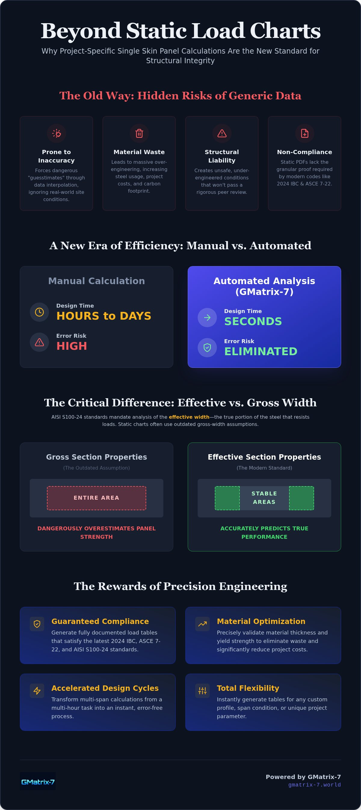
Effective width is the cornerstone of this analysis. In a profiled panel, the entire surface area does not contribute equally to load resistance. Under compressive stress, the central portions of wide, flat elements often buckle slightly, shifting the load toward the stiffer corners or ribs. Designers must calculate the effective section, which is the reduced cross-sectional area that remains stable under specific stress levels. Gross width is a purely physical measurement; effective width is a structural reality. If your calculations rely on gross section properties, you are likely overestimating the panel's capacity by a dangerous margin.
Calculating Section Properties for Profiled Panels
Determining the moment of inertia for a profiled panel is a multi-stage process. The stiffness of the section changes depending on whether it is subjected to positive pressure (wind pushing in) or negative suction (wind pulling out). Rib height and pitch dictate the inherent stiffness of the profile. A higher rib generally increases the moment of inertia, but it also increases the risk of web crippling at support points. You must account for the shift in the neutral axis as different parts of the profile become "effective" under varying load intensities. For engineers looking to streamline these complex iterations, utilizing a specialized LGS design module ensures that every rib and valley is analyzed according to the latest AISI standards.
Addressing Deflection and Strength Limits
Structural integrity is measured by two distinct criteria: serviceability and ultimate strength. Serviceability limits, typically expressed as L/180 or L/240, focus on deflection. While a panel might not snap, excessive bowing can cause aesthetic issues, seal failure, or water ponding. Ultimate strength, however, is a safety-critical limit where the panel or its fasteners reach total failure. Web crippling is the localized failure of a thin-walled section under concentrated loads. This often occurs where the panel rests on a purlin, requiring careful analysis of the bearing length and the specific profile geometry to prevent the web from crushing under high reaction forces. Failing to check for web crippling is one of the most common oversights in manual engineering workflows.
Manual vs. Automated Load Table Generation: A Comparative Analysis
Manual workflows are a legacy burden that modern engineering firms can no longer afford to carry. Performing a single skin panel load calculation by hand or through disconnected spreadsheets is a grueling exercise in redundancy. It often consumes hours of senior engineering time, requiring meticulous data entry for every span condition and load case. In contrast, automated systems process these complex variables in seconds. This isn't just about speed; it's about the depth of the analysis. Software allows you to iterate designs instantly, testing different gauges or rib heights to find the most cost-effective solution without restarting the entire calculation process. A professional, software-generated report commands authority during the peer review process, whereas handwritten or basic spreadsheet outputs often invite skepticism and additional scrutiny.
The disparity in error rates between these two methods is stark. Manual entry for complex multi-span conditions, such as triple-span or cantilevered scenarios, is where most structural failures begin. It's easy to miscalculate a peak stress point or a deflection limit when juggling multiple AISI S100-24 variables. Automation removes the human element from these repetitive mathematical cycles. By shifting to a data-driven approach, you ensure that every output is mathematically sound and fully optimized for the specific project requirements. This transition transforms the engineering department from a bottleneck into a driver of project speed and profitability.
The ROI of Automation in Structural Detailing
Efficiency in the design phase ripples through the entire project lifecycle. By reducing the man-hours spent on repetitive calculation tasks, firms can reallocate their top talent to higher-value design challenges. Precision in the design phase also eliminates costly fabrication errors. When your calculations are linked to automated bill of materials software, the transition from engineering to the factory floor is seamless. This integration ensures that the material ordered matches the structural requirements exactly, preventing over-ordering or the mid-project delays caused by insufficient stock. The result is a significantly accelerated approval drawing phase, backed by precise data exports that building officials can trust.
Flexibility in Non-Standard Scenarios
Real-world projects rarely follow the idealized conditions found in manufacturer catalogs. You'll often encounter cantilevered spans, varying snow load distributions, or the need for custom material yield strengths, such as 50 ksi versus 80 ksi steel. Automated systems handle these non-standard variables with ease. They allow you to input specific site data and receive an immediate, compliant single skin panel load calculation tailored to that exact environment. This flexibility is essential for projects spanning different global jurisdictions, where design codes and safety factors may vary. Seamlessly switching between standards ensures your firm remains competitive and compliant on an international scale.
Best Practices for Generating Project-Specific Cladding Load Tables
Engineering excellence demands systematic rigor. A reliable single skin panel load calculation is only as robust as the data fueling it. You must move beyond generalities and validate every material property before beginning the analysis. This process starts with confirming the base metal thickness (BMT). Designers often make the mistake of using the nominal coated thickness, which includes paint and metallic coatings that offer zero structural capacity. By using the true BMT and the certified yield strength, typically 50 ksi or 80 ksi, you ensure the resulting load tables reflect the panel's actual performance limits. Precision at this stage prevents the structural discrepancies that lead to field failures or costly redesigns.
Selecting the correct span condition is equally critical. A panel's behavior changes dramatically between a single span and a continuous triple-span configuration. Multi-span setups generally offer higher load capacities due to the redistribution of moments, but they also introduce higher reaction forces and the risk of web crippling at internal supports. You must apply the appropriate load combinations per ASCE 7-22 or your specific local building code to ensure structural equilibrium under both positive and negative pressures.
Step 1: Profile and Material Definition
Geometric fidelity is the foundation of section property analysis. You need to define rib height, pitch, and valley widths with absolute precision to calculate the moment of inertia correctly. It's also vital to account for manufacturing tolerances and the specific steel building purlin design software context. The panel doesn't exist in a vacuum; its performance is inextricably linked to the stiffness and spacing of the underlying support members. Validating these interfaces ensures that the entire cladding assembly, not just the panel, meets the required safety factors.
Step 2: Environmental and Structural Constraints
Site-specific environmental data must dictate your calculation parameters. Establish clear wind pressure zones based on the building's height, exposure category, and internal pressure coefficients. Corner zones (Zone 3) often face significantly higher suction forces than the field of the roof (Zone 1), requiring project-specific tables that account for these variations. For long-length panels, you can't ignore thermal expansion and contraction, which can induce stress on fasteners and substrates. If you're working with hybrid cladding systems, ensure your output formats align with sandwich panel load table software standards for a unified engineering documentation package.
The final pillar of a professional single skin panel load calculation is fastener verification. A panel is only as strong as its connection to the structure. You must verify both pull-out capacity from the purlin and pull-over capacity of the panel rib. These values are often the limiting factor in high-wind zones, overshadowing the panel's own flexural strength. Deploy the industry's most advanced tool for your next project by exploring the GMatrix-7 structural suite today to automate these complex checks with total confidence.
GMatrix-7: Revolutionising Load Table Generation for Single Skin Panels
GMatrix-7 / LGS (AISI) stands as the definitive solution for engineers who refuse to settle for the approximations of yesterday. While previous sections highlighted the technical pitfalls of manual entry and static charts, this module provides the precise mathematical engine required to master every single skin panel load calculation. It enables the automated load table generation for any custom profile, regardless of its geometric complexity. By centralising every single skin panel load calculation within a single, high-performance interface, the software ensures that your data remains consistent and your results remain unassailable. Integration with GMatrix-7 / MBS (IBC) facilitates a holistic engineering workflow where cladding and primary structural systems communicate perfectly. You'll generate professional, code-compliant documentation in minutes, transforming a task that once took days into a streamlined, high-value output.
Seamless Integration from Calculation to Fabrication
The value of GMatrix-7 extends far beyond the initial analysis phase. It bridges the divide between design and reality by automatically pushing load data into the Bill of Materials (BOM). This level of automation ensures that the material specifications on the shop floor align perfectly with the structural requirements established during the engineering phase. The software also generates comprehensive approval drawings that reflect the calculated capacities with absolute fidelity. By reducing the gap between engineering intent and shop floor execution, you eliminate the risk of miscommunication. Every panel is designed, ordered, and installed exactly as the math dictates, protecting both your reputation and your project's bottom line.
The Global Standard for Structural Automation
As a world-class entity, GMatrix-7 supports global fabricators through rigorous multi-code compliance. Whether your project adheres to the latest AISI S100-24 standards or international codes across Europe and Asia, the software adapts seamlessly to maintain high-register professional standards. This isn't just about providing a tool. It's about delivering the security and peace of mind that comes from using battle-tested, award-winning technology. With active industry awards in 2024, GMatrix-7 remains the guardian of safety and the primary driver of industrial progress in the structural engineering sector. Rely on a partner that values excellence above all else and provides the precision your professional reputation deserves.
Advancing Your Engineering Standards Through Automation
The shift from static manufacturer charts to dynamic, project-specific analysis represents the new standard in cladding engineering. By mastering the nuances of AISI S100-24 and moving beyond the limitations of manual spreadsheets, you protect your projects from the hidden risks of over-engineering and structural non-compliance. A precise single skin panel load calculation is no longer just a technical requirement; it's a strategic advantage that reduces material waste and accelerates project timelines across the building lifecycle.
GMatrix-7 delivers the award-winning structural design automation required to compete on a global scale. Our battle-tested technology ensures full IBC and AISI compliance while seamlessly integrating your engineering data with automated BOM and drawing generation. It's time to replace legacy workflows with world-class precision that global fabricators already trust for their most complex MBS and LGS projects. Streamline your structural engineering with GMatrix-7 today and experience the peace of mind that comes from industry-leading excellence. Your pursuit of superior design starts with the right tools.
Frequently Asked Questions
What is the difference between a load chart and a load calculation?
A load chart is a static, pre-calculated table based on generalized manufacturer test cases, while a project-specific single skin panel load calculation is a dynamic mathematical analysis tailored to your exact site conditions. Charts often force engineers to interpolate between fixed values, and this introduces hidden risks. In contrast, a calculation accounts for your precise purlin spacing, material yield strength, and unique wind zones, ensuring the resulting design is both safe and optimized for cost.
How does AISI S100 influence single skin panel design?
AISI S100-24 serves as the definitive technical standard for cold-formed steel members, specifically addressing the unique stability challenges of thin-gauge profiles. It requires engineers to calculate effective section properties rather than relying on gross geometry, accounting for local and distortional buckling. This standard ensures that your cladding remains structurally sound under extreme pressure, providing a rigorous framework for determining the ultimate strength and serviceability limits of profiled metal panels.
Can I use single skin load tables for sandwich panels?
You cannot use single skin load tables for sandwich panels because the structural mechanics are fundamentally different. Single skin panels rely on the flexural stiffness of the profiled metal, whereas sandwich panels involve composite action between two skins and a structural core. This core provides continuous shear support, significantly increasing the span capacity. Attempting to apply single skin data to a composite system will result in inaccurate designs that fail to account for core shear or thermal stress.
What are the most common errors in manual panel load calculations?
The most frequent errors in manual calculations include the incorrect use of gross section properties and the failure to check for web crippling at interior supports. Engineers often overlook the redistribution of moments in multi-span configurations or use outdated wind load standards. Manual interpolation between static chart values also leads to significant inaccuracy. These mistakes frequently result in either unsafe structural designs or massive over-engineering that inflates material costs and hurts project profitability.
How do I calculate wind uplift for single skin metal roofs?
To calculate wind uplift, you must first determine the site-specific pressures using ASCE 7-22, focusing on the higher suction forces found in building corners and edges. Once the pressures are established, perform a single skin panel load calculation to verify the panel's resistance to rib buckling. You must then validate the connection integrity by checking the fastener pull-out from the substrate and the pull-over capacity of the panel itself to ensure total assembly safety.
Does GMatrix-7 support custom rib profiles for load table generation?
GMatrix-7 provides total flexibility by allowing engineers to define any custom rib profile for automated load table generation. You aren't restricted to standard manufacturer geometries; you can input specific rib heights, pitches, and valley widths to reflect your exact product line. The software instantly calculates the effective section properties for these custom shapes, ensuring that your documentation remains precise and fully compliant with the latest AISI S100-24 structural requirements for cold-formed steel.
Is software-generated documentation acceptable for IBC 2024 compliance?
Software-generated documentation is fully acceptable for IBC 2024 compliance, provided the underlying engine adheres to the referenced standards like AISI S100. Modern building officials actually prefer the granular, project-specific data provided by automated reports over generalized manufacturer catalogs. GMatrix-7 generates rigorous structural documentation that clearly outlines the mathematical basis for every load capacity, ensuring your submittals move through the approval process with minimal scrutiny and maximum professional authority.
How does panel gauge affect the span-to-load ratio?
Increasing the panel gauge directly improves the moment of inertia and the inherent stiffness of the section, which significantly enhances the span-to-load ratio. A thicker gauge reduces the risk of local buckling in wide, flat elements, allowing the panel to maintain its effective width under higher compressive stresses. This allows for longer purlin spacings without exceeding deflection limits, such as L/180 or L/240, ultimately reducing the total weight of the secondary structural steel required for the project.


